Introduction
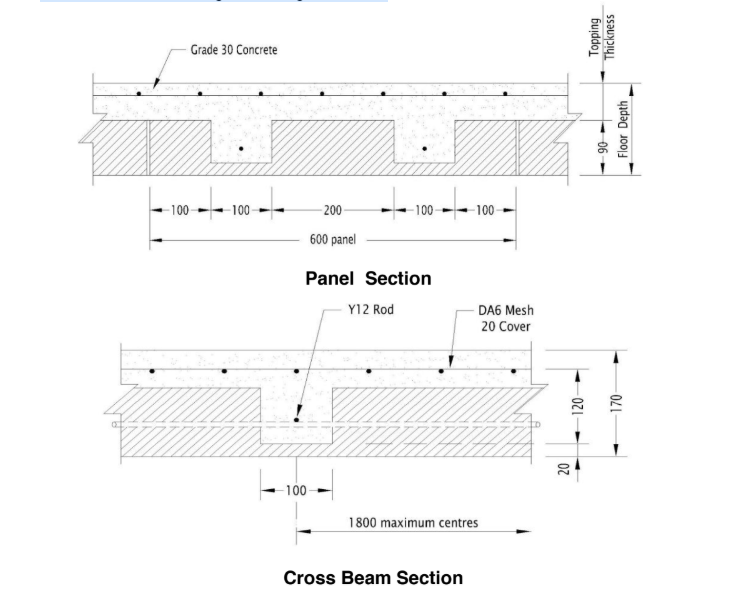
The product consists of rigid panels, which provides permanent formwork to a
ribbed reinforced concrete flooring system. The floor detailed in this manual is
suitable for residential floor requiring a fire resistance of 90 minutes with spans
up to 6.0 metres. This floor has a panel depth of 90 mm topped with 80 mm
concrete giving a structural floor depth of 150 mm and an overall floor thickness
of 170 mm. For other applications both floor depth and the topping thickness
can be varied to suit specific requirements.
What you see is what you get
Construction
1. Foundation slab is poured with starter bars cast in to align with the centre of the cores in the KOTO Panels.
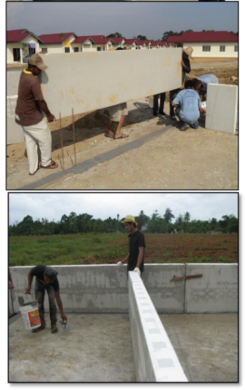
2. KOTO Panels are placed over the starter bars and glued in place.
3. Subsequent panels are glued as they are placed.
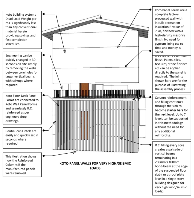
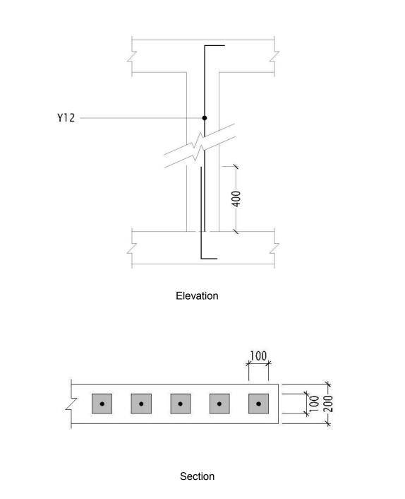
4. Vertical reinforcement is placed into the cores so that it laps with the starter bars at the bottom and extends into the slab above.
5. A horizontal bar is placed in lintels and any bond beams.
6. Columns are concreted.
7. The next floor slab is formed and cast.
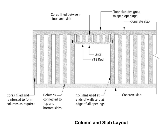
Design Application
a. Foundation and floors has sufficient strength and stiffness to provide lateral support and rotational restraint to the columns.
b. Roof and floors have adequate stiffness to distribute the racking forces to the columns.
c. Starter bars extending from the floors to provide anchorage at the bottom of the columns.
d. Cores are reinforced.
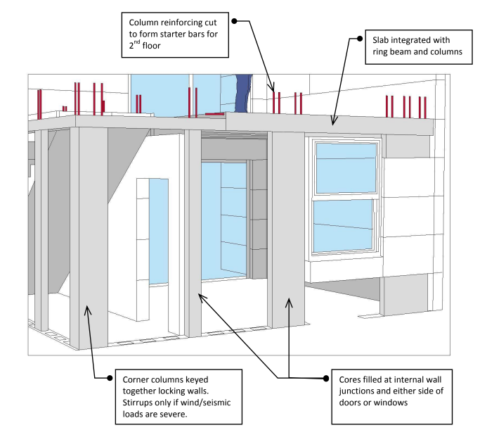
e. Column reinforcement extends into the slabs at the top to provide anchorage at the top of the columns.
f. Cores are concreted to form columns.
g. The columns all act together to carry the vertical loads from above and to resist lateral loads imposed on the building.
h. The floors act as beams between the columns.
i. Where the roof is not a concrete slab, then a bond beam must be used to connect all the columns together and to connect the roof to the walls.
K-Pods
Step 1: Place plastic sheet over properly prepared soil.
Step 2: Place plastic Spacers. These 4 way spacer insure the steel bar once placed in in exactly the correct place.
Step 3: Soil to slop 1-2 degrees away from the K-Pod Foundation
Step 4: All edge beams (perimeter beam) to be wider than the Koto 8 panel.
Step 5: In Asia a 450mm wide footpath is cast at the same time the concrete is poured floor slab.
Step 6: Place appropriate formwork so concrete can be poured.
Step 7: To prohibit termites from entering into the house via the plumbing pipe, place a square section of stainless steel mesh and secure with a stainless steel hose clamp prior to pouring the concrete
Step 8: Begin pouring concrete in accordance to the building code. It is more practical to concrete from the edges to the centre and work backwards to zero starting point.
Step 9: While placing concrete, insert the steel bars that have a 150mm long 90degree into the substrate. The engineer nominated size of bar to extend into the centre of the thickened edge beam & 450mm above the slab.

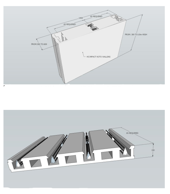
K-Wall
KOTO WALL PANEL FORMS
Koto Wall Panels to be bonded to the concrete floor slab over the starter bars as specified by the
engineer.
Bonding Compound:
Use Koto 2 pack J.B. Koto Joint Bond Paste for permanent bonding.
Koto 8 Wall Panels come pre-machine plastered with a mineral reinforced composite to both
sides of the panels.
Koto 8 Wall Panels have male and female connection joints on all faces of the Koto Panel. The male
connection always to the top of panel.
Koto J.B. Paste once mixed in a pail has a pot life of one (1) hour.
Insure the JB Paste is spread with a Notch Trowel for best results so the panel is securely bonded to
the substrate. - Do not apply and allow J.B. paste to stand in direct sunlight. Spread J.B. Paste and
immediately place the Koto Panel to the wet surface.
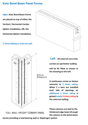
“T” Corner Partitions:
The floor plan will show where any R.C. core holes will be required, however, always J.B. Paste the partition walling to the external insulated walling system.

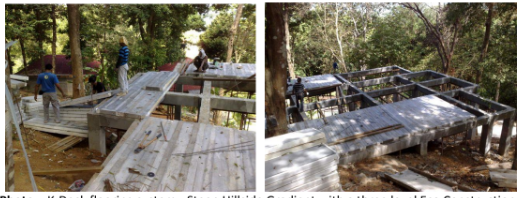
K-Deck
The K-Deck Flooring System can be viewed in the Multi-Level Manual for double story and
multi-level buildings that require a concrete floor slab.
The Koto K-Deck Floor Form can be installed with two different options.
Option 1: Stiffeners are bonded into the K-Deck Form ex-Factory. This is ideal where small
spans are common so that installers can quickly install the forms and immediately stand on
the platform without scaffolding beneath.
Option 2: Where large spans are required the K-Deck Forms are placed onto scaffolding
in the typical manner. Steel and concrete as per engineers shop drawings are then placed.
Cyclonic Load
The wind load is calculated by the amount of core holes filled, as well as the reinforcement used.
The system is basically reinforced concrete and will easily withstand cyclonic conditions, upon design by the engineer.

Video Demonstration
Manuals
Click on the button to download the Contractors Guide 6 - engineer details
Contractors Guide 6 - engineer details
Click on the button to download the KOTO DESIGN MANUAL
Click on the button to download the Cyclonic Load Document